[RMP 10.3.3]
The changelog for 10.3.2 includes this:
[General Change] Axis improved homing methods support low trigger state.
Can you summarize what is different? Are there new API functions, or differences in behavior with current API functions?
[RMP 10.3.3]
The changelog for 10.3.2 includes this:
[General Change] Axis improved homing methods support low trigger state.
Can you summarize what is different? Are there new API functions, or differences in behavior with current API functions?
I’m seeing some unexpected behavior with my code that worked fine (before upgrading) for methods 119/121. It appears to be skipping the stage 1 move (even though the input is low).
We discussed this in our Dec.16 email. Subject: 10.3.2. Pasting here for others:
Works with the methods which are named “Improved” here:
Should work with dedicated OR custom home input.
Diagrams updated here:
Use HomeTriggerStateSet(false) if you are low-active and things should work as expected.
Is the unexpected behavior using the high or low active trigger state?
I’m not calling HomeTriggerStateSet(...) at all. Is that a problem?
…but it’s active high.
Give me a moment and I’ll investigate this on one of our AKD demo units and get back to you.
Active high is the default settings, so you shouldn’t need HomeTriggerStateSet if you are active high.
Merely switching back to 10.3.1 changes the behavior I observe with Home(...).
I’m using these methods:
RSIHomeMethodImprovedPOSITIVE_HOME_NEGATIVE_MOMENTUMRSIHomeMethodImprovedNEGATIVE_HOME_POSITIVE_MOMENTUMTesting it on my AKD I’m seeing the expected behavior for these two methods.
Could you do some testing in RapidSetup on your system?
Try HomeTriggerStateSet(LOW)? Skipping a stage would be a symptom that makes sense if this was set opposite of what it should be. When the switch is depressed what does the Dedicated I/0 HomeInput show in Rapid Setup?
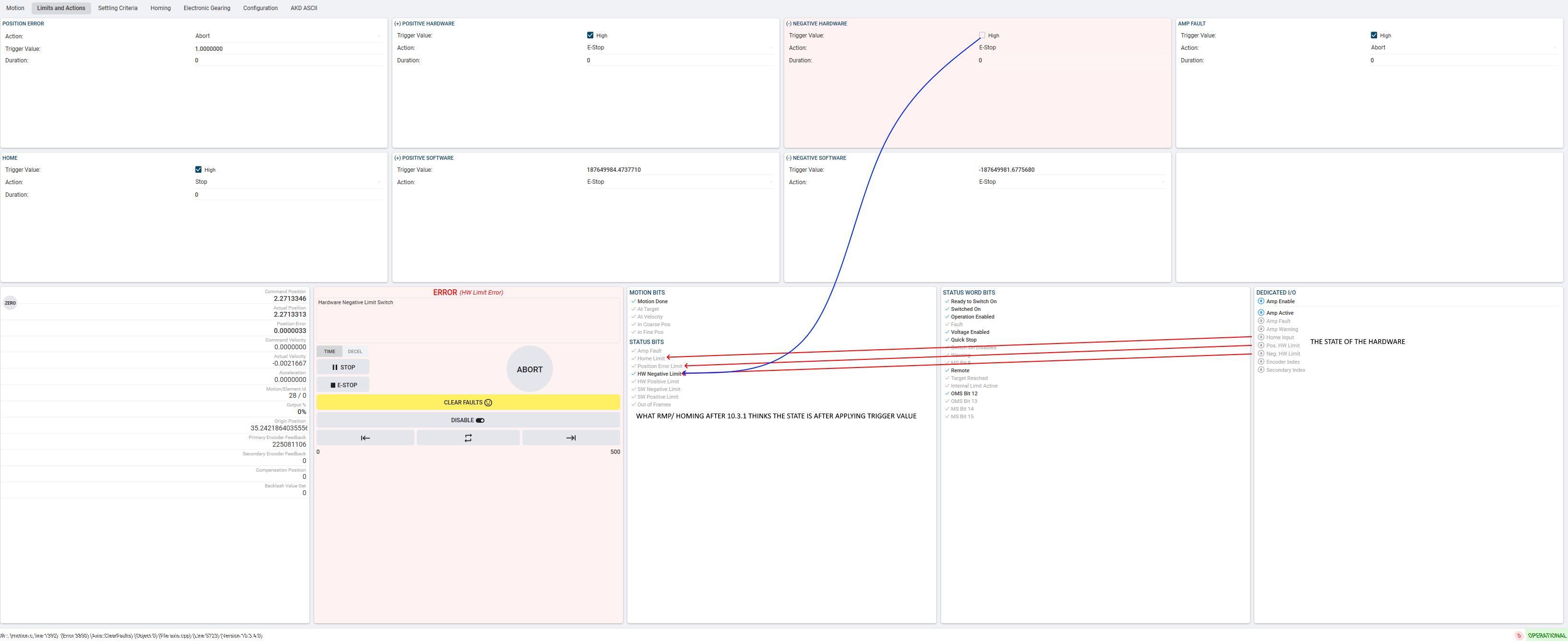
You may need to call HardwareNegLimitTriggerStateSet() or HardwarePosLimitTriggerStateSet() now when you wouldn’t have needed to in 10.3.1 As those limits could be in an incorrectly active state during the homing routine now causing it to error out.
You will get a message like this in RapidSetup if the state of the +/- limit is the issue during homing.
(I probably should have provided more info on my scenario…)
I’m using HomeLimitCustomConfigSet(...) for this operation.
Here are the API calls I’m making to configure/invoke homing.
rmp_axis->HomeMethodSet(home_method1);
rmp_axis->HomeLimitCustomConfigSet(use_io_addr,use_io_bit);
rmp_axis->HomeBehaviorSet(r::RSIAction::RSIActionTRIGGERED_MODIFY);
rmp_axis->HomeVelocitySet(r::RSIHomeStage::RSIHomeStageSTAGE_ONE,home_velocity);
rmp_axis->HomeVelocitySet(r::RSIHomeStage::RSIHomeStageSTAGE_TWO,backoff_speed_puu);
rmp_axis->HomeVelocitySet(r::RSIHomeStage::RSIHomeStageSTAGE_THREE,home_velocity);
rmp_axis->HomeVelocitySet(r::RSIHomeStage::RSIHomeStageSTAGE_FOUR,home_velocity);
rmp_axis->HomeAccelerationSet(home_acceleration);
rmp_axis->HomeDecelerationSet(home_acceleration);
rmp_axis->HomeJerkPercentSet(home_jerk_pct);
rmp_axis->StopTimeSet(new_stop_time);
rmp_axis->Home(DO_NOT_MOVE_TO_ZERO);Is there a way to test homing to an arbitrary I/O in RapidSetup?
Ahh, I should have remembered.
I can monitor the state of those bits in RapidSetup while my app does the homing, if that would provide meaningful information.
Unfortunately not.
Would monitoring any firmware addresses provide meaningful info?
I’ve got a trace (ALL) of the config/home.
In my “ordinary” testing, I capture firmware data for the input. In all my observations, it’s always been low at the start of Home(...).
The input you are recording here is the arbitrary hardware input for your home and not the RMP Home Limit correct?
And you are physically off the switch at the start?
Implying the hardware is sending an Active HIGH type of signal to RMP.
I haven’t tested this homing routine with a HomeLimitCustomConfigSet() yet but it should work.
I would be very curious what behavior you get on your system if you call HomeTriggerStateSet(0) even though this is the opposite of what you are telling me the configuration should be.
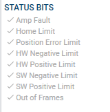
Please also observe in Rapid Setup or your recorder if the STATUS BITS HW Positive Limie or HW Negative limit remain LOW during homing.
I tested it calling HomeTriggerStateSet(false)
The same basic misbehavior occurs.
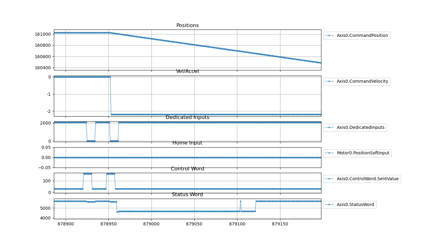
As for details, here’s a plot of some information. I captured the dedicated inputs (hoping this would correspond to the bits you need).
The view is zoomed to ~50 ms before homing starts (when the commanded velocity changes).
The dedicated inputs only over has two values: 0, 2048.
In RapidSetup, I see “Home Limit” on before I start moving. I would guess that this is how RMP is concluding that it should start with stage 2.
Here’s the Product element for the drive in question. I don’t see anything defined for “home” in the inputs elements.
  <Product Code="0x10006">
    <ProductName>D3_America EtherCAT Drive (CoE)</ProductName>
    <ShortName>CTB D3</ShortName>
    <ItemSubType>Drive</ItemSubType>
    <AxisCount>3</AxisCount>
    <StatusWord>Inputs.Status word0</StatusWord>
    <PositionActual>Inputs.Position actual value0</PositionActual>
    <VelocityActual>Inputs.Velocity actual value0</VelocityActual>
    <TorqueActual>Inputs.Torque actual value0</TorqueActual>
    <ControlWord>Outputs.Control word0</ControlWord>
    <PositionDemand>Outputs.position set point (PCMD)0</PositionDemand>
    <VelocityDemand>Outputs.velocity set point (VCMD)0</VelocityDemand>
    <TargetTorque>Outputs.Target torq0</TargetTorque>
    <GeneralInputs Size="2">Inputs.Digital0 input status</GeneralInputs>
    <ModeOfOperation>Outputs.Modes of operation0</ModeOfOperation>
    <GeneralOutputs Size="2">Outputs.Digital0 output control</GeneralOutputs>
    <IO>
      <DigitalInputItems>
        <DigitalInput SigBits="0xFFFF" Size="16">Inputs.Digital0 input status</DigitalInput>
        <DigitalInput SigBits="0xFFFF" Size="16">Inputs.Digital1 input status</DigitalInput>
        <DigitalInput SigBits="0xFFFF" Size="16">Inputs.Digital2 input status</DigitalInput>
      </DigitalInputItems>
      <DigitalOutputItems>
        <DigitalOutput SigBits="0xFFFF" Size="16">Outputs.Digital0 output control</DigitalOutput>
        <DigitalOutput SigBits="0xFFFF" Size="16">Outputs.Digital1 output control</DigitalOutput>
      </DigitalOutputItems>
    </IO>
    <AdditionalAxes>
      <Axis Index="1">
        <StatusWord>Inputs.Status word1</StatusWord>
        <PositionActual>Inputs.Position actual value1</PositionActual>
        <VelocityActual>Inputs.Velocity actual value1</VelocityActual>
        <TorqueActual>Inputs.Torque actual value1</TorqueActual>
        <ControlWord>Outputs.Control word1</ControlWord>
        <PositionDemand>Outputs.position set point (PCMD)1</PositionDemand>
        <VelocityDemand>Outputs.velocity set point (VCMD)1</VelocityDemand>
        <TargetTorque>Outputs.Target torq1</TargetTorque>
        <ModeOfOperation>Outputs.Modes of operation1</ModeOfOperation>
      </Axis>
      <Axis Index="2">
        <StatusWord>Inputs.Status word2</StatusWord>
        <PositionActual>Inputs.Position actual value2</PositionActual>
        <VelocityActual>Inputs.Velocity actual value2</VelocityActual>
        <TorqueActual>Inputs.Torque actual value2</TorqueActual>
        <ControlWord>Outputs.Control word2</ControlWord>
        <PositionDemand>Outputs.position set point (PCMD)2</PositionDemand>
        <VelocityDemand>Outputs.velocity set point (VCMD)2</VelocityDemand>
        <TargetTorque>Outputs.Target torq2</TargetTorque>
        <ModeOfOperation>Outputs.Modes of operation2</ModeOfOperation>
      </Axis>
    </AdditionalAxes>
  </Product>
Note: This NodeInfo Product didn’t change between RMP versions that I was testing.