Hello team,
I’m on 10.4.2.
Using the documentation about MDP, I have now set up a bus coupler from company called Innovance with some IO slots attached. Bus coupler is called GL20.
Physically it looks like this: Bus Coupler, slot with 16 DO, slot with 16 DI, slot with 4 AO, slot with 4 AI.
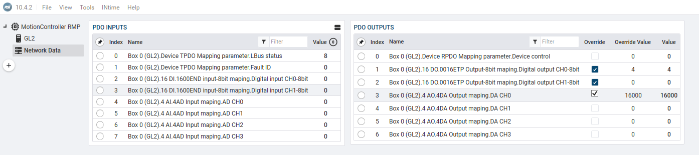
Through the page “Network Data” in RapidSetup I can read and write to all slots and all channels succesfully. I attach a screenshot of this page.
I would like the inputs and outputs to also show up in the “normal” RapidSetup page called IO. Where I can toggle them and set values more easily.
Is this possible?
I think this is where the DigitalInputs tag in NodeInfo.xml is useful for me, but I’m not sure.
I’m unsure how a variable network with this MPD device works together with the tags.
For example when I add one more 16 channel DI slot, how would the PDO name be incremented, and could I account for this new name in the CustomNodeInfo.xml and the DigitalInputItems section. I see for example the “HAS” tag in the documentation, but don’t really understand how to apply it in this scenario.
To be a little bit less abstract. Does this look like a good start to get the digital inputs set up correctly?
<IO>
          <!-- Optional - DigitalInputItems: Add in PDOEntries you want to be identified as Digital Inputs. -->
          <DigitalInputItems>
            <!-- Required - DigitalInput: One or more entries to evaluate. -->
            <!-- Required - SigBits: Specific which bits in the associated PDO entry are treated as IO. This is a bit mask.  Most DS402 IO starts in the upper 4 bytes. -->
            <!-- Required - Size: (In bits) Normally this will be 8, 16, or 32 -->
            <!-- Optional - Home | PosLimit | NegLimit: (Bit Index) Represent DedicatedIO which are automatically tied in with RSI events associated with the axis. -->
            <!-- Required - Value: String to help us find the associated PDO Entry. -->
            <DigitalInput SigBits="0xFF" Size="8">16 DI.1600END input-8bit maping.Digital input CH0-8bit</DigitalInput>
            <DigitalInput SigBits="0xFF" Size="8">16 DI.1600END input-8bit maping.Digital input CH1-8bit</DigitalInput>
        </IO>
mdp.xml looks like this.
<?xml version="1.0" encoding="utf-8"?>
<Mdp xmlns:xsd="http://www.w3.org/2001/XMLSchema" xmlns:xsi="http://www.w3.org/2001/XMLSchema-instance">
  <Topology>
    <Node address="1001">
      <Slot number="1" moduleIdent="0x10f41024">16 DO</Slot>
      <Slot number="2" moduleIdent="0x10f41010">16 DI</Slot>
      <Slot number="3" moduleIdent="0x10f41030">4 AI</Slot>
      <Slot number="4" moduleIdent="0x10f41040">4 AO</Slot>
    </Node>
  </Topology>
  <Location>
    <Scan deviceType="0x1389" start="0xF050" delta="0x0" depth="8" primary="0x10" />
    <Scan deviceType="0x184C1389" start="0x9000" delta="0x10" depth="8" primary="4" secondary="5" />
  </Location>
  <LookupTable>
    <Item key="10f41024" moduleIdent="0x10f41024">16 DO</Item>
    <Item key="10f41010" moduleIdent="0x10f41010">16 DI</Item>
    <Item key="10f41030" moduleIdent="0x10f41030">4 AI</Item>
    <Item key="10f41040" moduleIdent="0x10f41040">4 AO</Item>
  </LookupTable>
  <Default moduleIdent="0x80000081">Default Entry</Default>
</Mdp>
NodeInfo.xml right now looks like this:
    <Vendor Id="0x100000">
      <VendorName>Innovance</VendorName>
      <Product Code="0x10F41000">
        <ProductName>GL20 EtherCAT Slave coupler</ProductName>
        <ShortName>GL2</ShortName>
        <ItemSubType>Box</ItemSubType>
      </Product>
    </Vendor>
I have uploaded the device’s ESI file here, should it be useful: GL20-RTU-ECT_1.3.5.0.xml - Google Drive